200EJB560 Gardner Denver 200EJB560 Type - S Air Compressor Controller
328-2
Free
The
Gardner Denver Starter/ControlBox - The following control components are located on the Gardner Denver 200EJB560 starter/control box.
Hourmeter - A continuous reading (non reset) type hourmeter displays the accumulated operating time of the unit and provides a convenient means for scheduling changes of oil and servicing of filters and other devices.
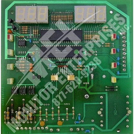
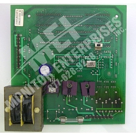
The GardnerDenver 200EJB560 Microprocessor Controller with keypad Monitors and controls compressor operation.
Emergency Stop Pushbutton Removes power from the Gardner Denver 200EJB560 microprocessor controller outputs to provide a positive means of stopping the unit in an emergency situation.
The
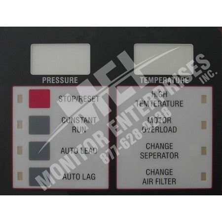
Gardner Denver STOP/RESET Button with LED This button is used to stop the compressor under ordinaryconditions. It is also used to extinguish any fault LEDs that are illuminated.The LED is illuminated whenever the unit is stopped for any reason EXCEPT anormal shutdown in one of the AUTO modes. A flashing LED indicates that areset is required.
CONSTANT RUN Button with LED - This button is used to operate the unit in the CONSTANT RUN mode. In this mode, the compressor runs continuously, loading and unloading in response to air demand. It will continue to run until stopped, either manually or by a protective shutdown. The LED is illuminated at all times while running in this mode.
AUTO LEAD Button with LED - This button is used to operate the unit in the Auto-Start-Timed-Stop mode, either by itself, or as the lead compressor in a Lead/Lag arrangement. Loading and Unloading occurs as in the CONSTANT RUN mode, however, if the compressor runs unloaded for a period of 10 minutes the unit is stopped. At this point the compressor remains in the AUTO LEAD mode and will restart when the system pressure reaches the load setpoint. The LED will remain illuminated throughout the cycle.
WARNING
Unit can automatically restart causing personal injury.
Disconnect, tag and lockout the power supply to the starter.
AUTO LAG. Button With LED - This button is used to select the lag unit in a lead-lag arrangement. Operation is identical to AUTO LEAD except that the start-load and unload setpoints are automatically 5 PSI lower than programmed.
NOTICE
Any mode may be selected at any time without stopping the compressor.
HIGH AIR TEMPERATURE LED - This LED is used to indicate an over temperature condition at the discharge of either cylinder. At the time of a high temperature shutdown, the LED is illuminated and the temperature digital readout is locked on to the offending temperature. Illumination of the decimal point in the lower right hand corner of the digital readout indicates that the temperature displayed is at the 1st stage discharge. A non-illuminated decimal point indicates 2nd stage discharge. Pressing STOP/RESET will extinguish the LED (if the temperature has lowered below 550 ºF) and revert the digital readout to displaying actual discharge temperature.
MOTOR OVERLOAD LED - This LED indicates that the motor overload relay has tripped. The overload relay itself must be reset before pressing STOP/RESET which will extinguish the LED.
Pressure and Temperature Digital Readouts. - These readouts normally indicate pressure and temperature at the 2nd stage discharge. See High Air Temperature LED (above) for a description of readout action during a high temperature condition. Alternately these readouts can be selected to display 1st stage discharge pressure and air temperature. To obtain such display while the compressor is running simply press the operating mode button that corresponds to the current operating mode of the unit.
(For example: If the unit is operating in the AUTO LEAD mode, press the AUTO LEAD button.) This will cause the readout to display the alternate parameters. This alternate display mode is indicated by illuminated decimal points in the lower right hand corner of each display. After releasing the button, the display will revert to its normal mode in 5 seconds.
The Gardner Denver 200EJB560 pressure digital readout will display interstage pressure whenever an interstage pressure of 50 PSI or greater is detected. Whenever interstage pressure is displayed, the lower, right hand decimal point will be illuminated.The purpose of this is to alert the operator to abnormally high interstage pressures.
ERROR MESSAGES The Gardner Denver 200EJB560 digital readouts are also used to display Error Messages. These error messages correspond to various indications concerning conditions of the pressure and temperature sensors and the Emergency Stop condition.
An Error Message will stop the compressor if running and prevent it from restarting. The failed sensor must be replaced to clear the error.
Any condition requiring the control panel to be reset will be indicated by a flashing STOP/RESET LED. If all readouts and LEDs are flashing, a power interruption has occurred, requiring the control panel to be reset.
Gardner Denver Pressure Readout
Gardner Denver Error #
Meaning
Error #
Meaning
E01
Failure of 2nd Stage Pressure Sensor
E01
Failure of 2nd Stage temperature sensor
E02
Failure of 1st Stage Pressure Sensor
E02
Failure of 1st Stage temperature sensor
E03
Failure of both pressure sensors
E03
Failure of both temperature sensors
E04
EMERGENCY STOP


